Push-rod Conveyor
Long conveying distances for metal chips, with coolant drainage
Push-rod conveyors move short, long and tangled metal chips over long distances while allowing large volumes of coolant to drain away. KÖBO ECO>PROCESS adapts the trough design, usable width, conveying distance and hydraulic drive to the chip volume, coolant flow rate and production layout.
METALWORKING
◆
Machining
◆
AUTOMOTIVE INDUSTRY
◆
Mechanical Engineering
◆
Centralized chip removal
Overview
Push-rod conveyors from KÖBO ECO>PROCESS
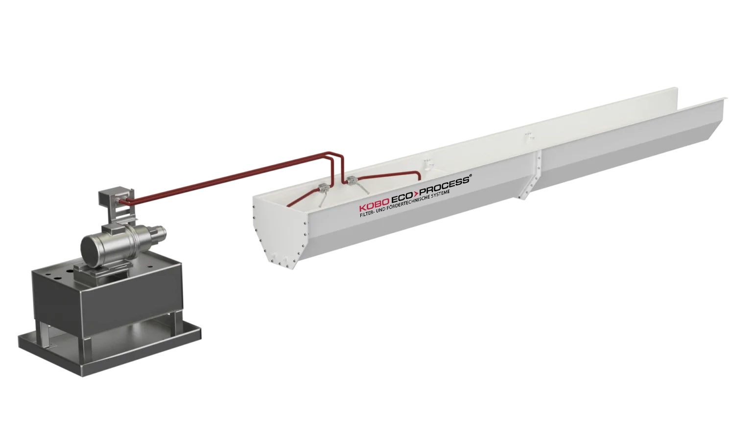
A push-rod conveyor, also known as a harpoon conveyor, is a hydraulically driven system for transporting short, long and tangled metal chips. It is particularly suited to moving large volumes of chips along long, predominantly horizontal routes.
A push rod guided inside the conveyor trough moves the chips toward the discharge point with each forward stroke. At the same time, coolant can drain along the sloped trough.
Push-rod conveyors are particularly suitable for centralized systems that collect chips and coolant from multiple machine tools or production areas and feed them to a central processing, filtration or disposal system.
KÖBO ECO>PROCESS designs conveying runs of up to 200 meters per push-rod conveyor. The trough cross section and height, stroke length and hydraulic power are matched to the volume of material, the amount of coolant and the installation conditions.

Design of a push-rod conveyor
➔
Conveyor trough with retaining elements: The trough collects chips and coolant from the connected machines or production areas. Retaining elements, such as hooks on the trough walls, prevent the chips from sliding all the way back during the return stroke. Trough height, width and slope are matched to the chip volume, coolant flow rate and site conditions.
➔
Push rod with pushers: The pushers attached to the hydraulically driven rod move the chips toward the discharge point during the forward stroke. As the rod returns to its starting position, the retaining elements hold most of the chips in place.
➔
Hydraulic drive: A hydraulic cylinder moves the push rod back and forth in controlled strokes. Depending on the system design, one hydraulic power unit can drive several push-rod conveyors.
➔
Flexible installation options: Push-rod conveyors can be installed in channels below the floor or close to floor level. Where the design allows, they can also be mounted on supports or suspended. This makes it possible to fit the conveyor into existing production areas and accommodate complex routes.
How a push-rod conveyor works
1.
Material intake
Chips and coolant enter the conveyor trough from the connected machine tools.
2.
Forward stroke
The hydraulic cylinder moves the push rod and its attached pushers forward in a controlled stroke.
3.
Chip transport
The pushers engage the chips and move them along the trough toward the discharge or transfer point.
4.
Return stroke
The push rod returns to its starting position while the retaining elements hold most of the chips in place. Repeated forward and return strokes move the chips progressively along the trough.
5.
Chip transfer
At the end of the conveying route, the chips are transferred to a bunker, another conveyor or a downstream processing system.
6.
Coolant drainage
As the chips are conveyed, coolant flows down the sloped trough to the designated drains or transfer points.
BENEFITS
Advantages of a push-rod conveyor
➔
Long conveying distances: A push-rod conveyor can collect chips from several machines or production areas and carry them to a common disposal or processing system.
➔
Handling different chip shapes: The conveyor can handle short, long, spiral or tangled metal chips. Its design is matched to the chip shape, material, chip volume and amount of coolant.
➔
Drainage of large coolant volumes: A properly sized trough with a suitable slope allows large volumes of coolant to drain in a controlled way while chips are being conveyed.
➔
Low maintenance requirements: The conveyor operates without a continuous belt or long conveyor chains, so there are relatively few moving parts along the conveying route. Depending on the chip type and system design, additional flushing nozzles may be unnecessary.
➔
Shared hydraulic drive: Depending on the design, one hydraulic power unit can drive several push-rod conveyors, reducing the number of separate drive units in a centralized system.
➔
Flexible integration: The conveyor cross section and installation method can be adapted to the building, machine layout and transfer points. Installation below the floor leaves more production space available.
➔
Automated material flow: Continuous removal of chips and coolant reduces the need for manual handling and helps keep production running smoothly.
Use
Typical applications for push-rod conveyors
Push-rod conveyors are used where large volumes of metal chips from several machines need to be collected and carried over long distances to a central transfer point.
➔
Metalworking and machining: Conveying short, long, spiral or tangled metal chips from turning, milling, drilling and other machining processes.
➔
Machine tools and machining centers: Collecting chips and coolant from several machines or linked production cells.
➔
Automotive industry: Removing large volumes of chips and coolant from engine, transmission and component production.
➔
Mechanical engineering: Connecting several machine tools to central collection, filtration or treatment systems.
➔
Centralized chip removal: Moving chips from different production areas to bunkers, shredders, centrifuges, briquetting presses or collection containers.
➔
Chip processing and material recovery: Feeding metal chips to downstream equipment for shredding, oil removal, drying or further recovery.
➔
Coolant drainage: Routing large volumes of coolant to central filtration and treatment systems, depending on the trough slope, cross section and system configuration.
Specifications
Technical specifications of the push-rod conveyor
Typical materials
Short, long, spiral and tangled metal chips, as well as bundles of chips
Width / usable width
400 to 1,000 mm
Conveying distance
Up to 200 m per push-rod conveyor, depending on the material, system layout and design
Stroke length
Approx. 1.5 m
Coolant Flow Rate
Up to 10,000 L/min. Higher flow rates are subject to individual project assessment.
Drive
Hydraulic drive with controlled forward and return strokes
Installation Options
Below floor level or close to the floor. Mounting on supports or suspension is possible depending on the project.
System configuration
As a standalone push-rod conveyor or as part of a centralized chip and coolant handling system
Note
Actual performance depends on chip shape, chip volume, the proportion of coolant in the conveyed material, the cross section of the conveyor trough, the conveying distance and the installation conditions.
Service
What we offer
Decades of experience
KÖBO ECO>PROCESS has decades of experience developing and building industrial conveyor systems for metal chips, coolant and metal scrap from production.
Complete solutions from a single source
We assess your conveying requirements and take care of design, manufacturing, installation and commissioning. We continue to support you once the system is in operation.
Tailored to your production needs
We adapt the usable width, trough cross section, conveying route, hydraulic drive, transfer points and installation method to your production conditions.
Fast response times
Direct points of contact and coordinated processes help us respond quickly to technical questions, spare parts requests and any adjustments you need.
Dedicated support
KÖBO ECO>PROCESS supports you from your first inquiry through commissioning. Once your system is running, we can help with maintenance, spare parts and upgrades.
Planning a push-rod conveyor?
Tell us what you need to convey and how your production area is laid out. We’ll help you find a solution that fits your operation.
Related Products